
Since ESP8266 is now so popular, I’ve recently bought a NodeMCU board to try it. I selected this board because the latest version of the board is breadboard-friendly, integrates a USB to serial chip, and it can be powered by a simple USB to micro USB cable. I also noticed a ESP8266 tutorial with NodeMCU firmware by SwitchDoc Labs the other day (using ESP-12 and Adafruit Huzzah), which I applied to my NodeMCU board, but since I encountered a few issues, I decided to report my findings, and write my own little getting started guide to switch on/off LED and GPIOs using a web interface.
NodeMCU v0.9 and NodeMCU v1.0
If you are going to purchase a NodeMCU board it’s important to know there are two official versions:
- NodeMCU v0.9 with ESP-12 module
- NodeMCU v1.0 with ESP-12E module
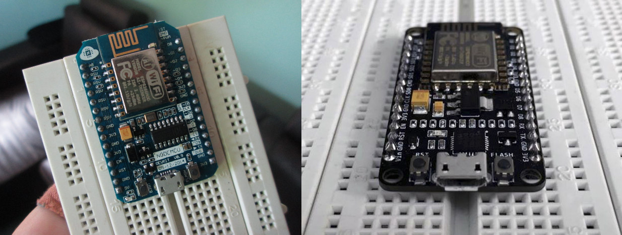
The main complain about NodeMCU v0.9 is that while it fits on the breadboard, you can’t use as it takes the full width of the board, while NodeMCU v1.0 is really breadboard-friendly as you can see on the right part of the picture above.
I’ve bought mine for just above $6 on eBay advertised as “NEW Version NodeMcu Lua ESP8266 WIFI Internet Development Board Latest Firmware”. The image was still v0.9, but since there are only two version, I was sort of expecting to receive NodeMCU v1.0. I was wrong…
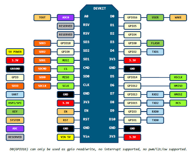
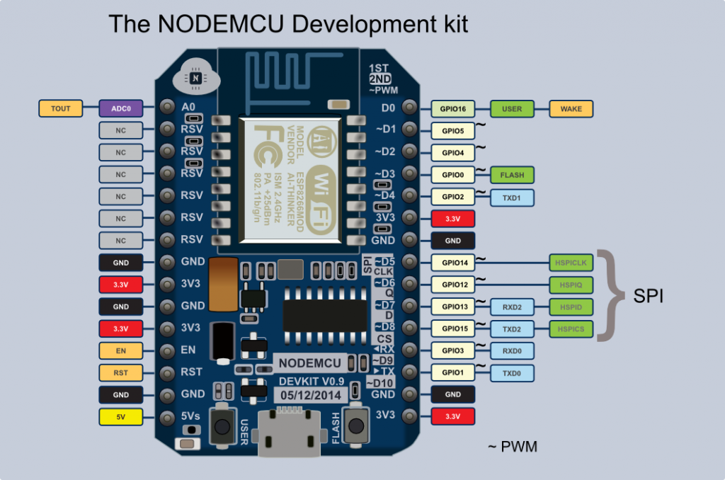
Other differences are that NodeMCU v1.0 has some extra GPIOs. Please find the pinout for both versions below. We’ll use these a little later in this tutorial.
Using NodeMCU v0.9 with a Breadboard
If you are lucky (or smart) enough to have purchased a NodeMCU v1.0 board, you can skip this section, but if you are stuck with NodeMCU v0.9 this may be useful.
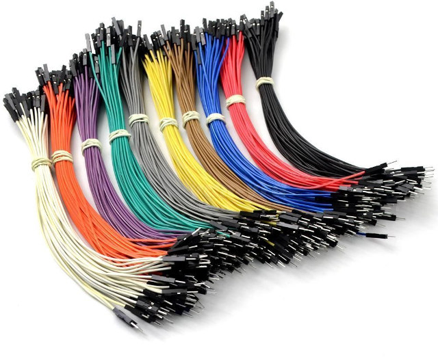
The first way is to connect the board to the breadboard using female to male Dupont cables.
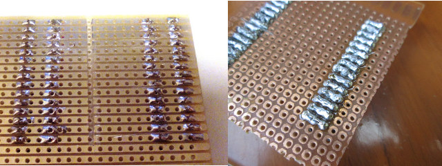
This works, but it’s not quite a neat as the solution provided on lucstechblog, that is making an adapter board with four female headers allowing to insert NodeMCU v0.9 board, and connecting male Dupont cables to the breadboard.
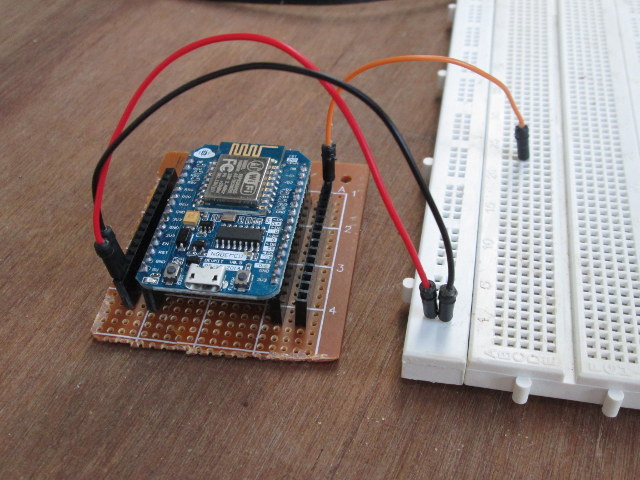 Luc uses a stripboard, which makes it quite easier to solder than the perfboard I used, and it took me a little while to get rid of some shortcuts I did during soldering. So I should get myself some stripboards too, as they may be useful in the future.
Installing Firmware and Accessing the Console on NodeMCU
Now that we have taken care of the hardware part, let’s check how to actually use the board. I was expecting some easy to follow documentation, but the documentation on NodeMCU.com is not really that useful to get started, and after searching further I eventually ended up on NodeMCU Firmware Wiki on github which provides more details.
However, after connecting the board to my computer via a micro USB to USB cable, while I could see new open ESSID “AI-THINKER_F52E3F” to which I could connect, I had no access to any webserver or the console. So I used minicom in Ubuntu to access the serial program (Putty can be used instead Windows), but again I had nothing. My default settings is 115200 8N1, so I tried 19200 and 38400, and 56700 without any luck.
The I decided to flash the latest NodeMCU firmware with esptool as explained on that guide. I did so in a terminal in an Ubuntu computer, with the board connected via USB.
- Download the latest firmware @ https://github.com/nodemcu/nodemcu-firmware/releases. There are both float and integer versions, but since I just wanted to toggle GPIOs, I downloaded the integer version:
1wget https://github.com/nodemcu/nodemcu-firmware/releases/download/0.9.6-dev_20150704/nodemcu_integer_0.9.6-dev_20150704.bin - Install esptool from Github
1git clone https://github.com/themadinventor/esptool.git - Flash the firmware
12345sudo python ./esptool.py --port /dev/ttyUSB0 write_flash 0x00000 ../nodemcu_integer_0.9.6-dev_20150704.bin[sudo] password for jaufranc:Connecting...Erasing flash...Writing at 0x00048000... (65 %)
and once it is successful:
123Wrote 450560 bytes at 0x00000000 in 44.3 seconds (81.3 kbit/s)...Leaving...
So I tried again to connect to the serial console via minicom, and no luck. I could still see the AI-THINKER_XXXXXX ESSID though, so it’s likely the board already came with the right firmware. Finally, I found that the serial console may be connected at 9600 baud on Electrodragon Wiki, so I changed the serial in minicom to 9600 8N1, and I had success with the Hello World test:
|
1 2 |
> print("Hello World") Hello World |
Controlling ModeMCU’s GPIOs via a Web Interface
Now that we know the board it working, we can run a small web server to control some GPIOs and LEDs. To do so, I created init.lua file with the code I found in SwitchDoc Labs’ tutorial:
|
1 2 3 4 5 6 7 8 9 10 11 12 13 14 15 16 17 18 19 20 21 22 23 24 25 26 27 28 29 30 31 32 33 34 35 36 37 38 39 |
wifi.setmode(wifi.STATION) wifi.sta.config("ROUTER_ESSID","WIFI_PASSWORD") print(wifi.sta.getip()) led1 = 3 led2 = 4 gpio.mode(led1, gpio.OUTPUT) gpio.mode(led2, gpio.OUTPUT) srv=net.createServer(net.TCP) srv:listen(80,function(conn) conn:on("receive", function(client,request) local buf = ""; local _, _, method, path, vars = string.find(request, "([A-Z]+) (.+)?(.+) HTTP"); if(method == nil)then _, _, method, path = string.find(request, "([A-Z]+) (.+) HTTP"); end local _GET = {} if (vars ~= nil)then for k, v in string.gmatch(vars, "(%w+)=(%w+)&*") do _GET[k] = v end end buf = buf.."<h1> ESP8266 Web Server</h1>"; buf = buf.."<p>GPIO0 <a href=\"?pin=ON1\"><button>ON</button></a> <a href=\"?pin=OFF1\"><button>OFF</button></a></p>"; buf = buf.."<p>GPIO2 <a href=\"?pin=ON2\"><button>ON</button></a> <a href=\"?pin=OFF2\"><button>OFF</button></a></p>"; local _on,_off = "","" if(_GET.pin == "ON1")then gpio.write(led1, gpio.HIGH); elseif(_GET.pin == "OFF1")then gpio.write(led1, gpio.LOW); elseif(_GET.pin == "ON2")then gpio.write(led2, gpio.HIGH); elseif(_GET.pin == "OFF2")then gpio.write(led2, gpio.LOW); end client:send(buf); client:close(); collectgarbage(); end) end) |
You’ll just need to change the second line replacing ROUTER_ESSID and WIFI_PASSWORD by your own credentials to have NodeMCU connect to your WiFi router. The code is set to modify the status for GPIO 0 and GPIO 2 (D3 and D4 pind on NodeMCU board as show in the pinout diagram), so you may also want to modify the code to control the GPIOs required by your project. If you want to clearly understand LUA language, you may want to check out that PDF file provinding details about Lua Language 5.1.
We’ll also need another Python script (luatool) to push the file to the board:
|
1 |
git clone https://github.com/4refr0nt/luatool.git |
The first time I tried it the connection failed:
|
1 2 3 4 5 6 7 8 9 10 11 12 13 14 15 |
python luatool/luatool/luatool.py --port /dev/ttyUSB0 --src init.lua --dest init.lua --restart ->file.open("init.lua", "w") ERROR send string : 'file.open("init.lua", "w")' expected echo : 'file.open("init.lua", "w")' but got answer : '�������`fx��^^ff^@^X^X��^X�x^X^X�f~����`^F^Xx^@����^X�^^^@^X^^^@^X^X��~fx^Xfx`^F^X�ffile.open("init.lua", "w")' Traceback (most recent call last): File "luatool/luatool/luatool.py", line 172, in writeln("file.open(\"" + args.dest + "\", \"w\")\r") File "luatool/luatool/luatool.py", line 61, in writeln raise Exception('Error sending data to MCU\r\n\r\n') Exception: Error sending data to MCU |
So I tried again an it went through:
|
1 2 3 4 5 6 7 8 9 10 11 12 13 14 15 16 17 18 19 |
python luatool/luatool/luatool.py --port /dev/ttyUSB0 --src init.lua --dest init.lua --restart ->file.open("init.lua", "w") -> ok ->file.close() -> ok ->file.remove("init.lua") -> ok ->file.open("init.lua", "w+") -> ok ->file.writeline([==[wifi.setmode(wifi.STATION)]==]) -> ok ->file.writeline([==[wifi.sta.config("CNXSOFT_ESP8266","esp8266")]==]) -> ok ->file.writeline([==[print(wifi.sta.getip())]==]) -> ok ->file.writeline([==[led1 = 3]==]) -> ok ... ->file.writeline([==[end)]==]) -> ok ->file.writeline([==[]==]) -> ok ->file.flush() -> ok ->file.close() -> ok ->node.restart() -> ok --->>> All done << |
So for some reasons, the connection between the baord and my computer is not very stable, and I had another aborted connection when I tried again later. The important point is that you need to check the command went through without errors.
We can check the IP address in LUA console:
|
1 2 3 |
> print(wifi.sta.getip()) 192.168.0.106 255.255.255.0 192.168.0.1 > |
Now open a web browser (I used Firefox) and point it to the IP address (192.168.0.106 in my case).
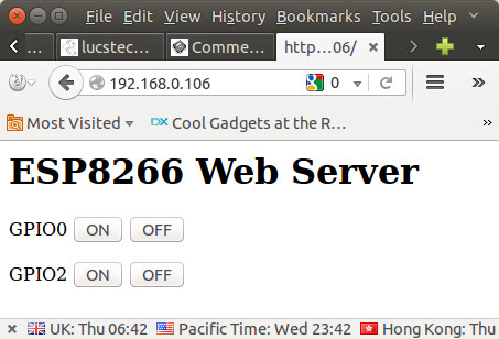 Now you can click on the On / Off button to change the GPIO levels, and with GPIO 2 it will also turn on and off the blue LED on ESP-12 module with OFF (low) = LED on and ON (high) = LED off. The URL will also change accordingly, for example GPIO 2 OFF will show the URL http://192.168.0.106/?pin=OFF2.
Finally, after some small challenges, NodeMCU is not that difficult to setup after all. Hopefully, this will help a few people getting started faster.

Jean-Luc started CNX Software in 2010 as a part-time endeavor, before quitting his job as a software engineering manager, and starting to write daily news, and reviews full time later in 2011.
Support CNX Software! Donate via cryptocurrencies, become a Patron on Patreon, or purchase goods on Amazon or Aliexpress