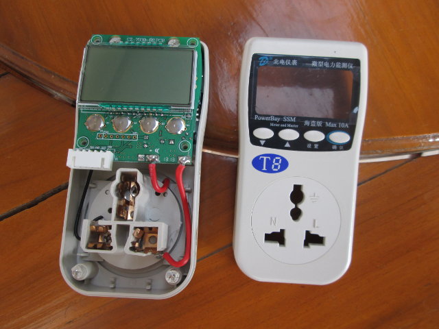
About two years ago, I purchased Northwest T8 power meter, and it worked fine for about three months, but one day the top plastic broke as as unplugged it, rubber bands prolonged its life for a few more weeks, but eventually the display stopped working, and keep it in my drawer for long while, until today, when I decided to have a closer look at how it was done.

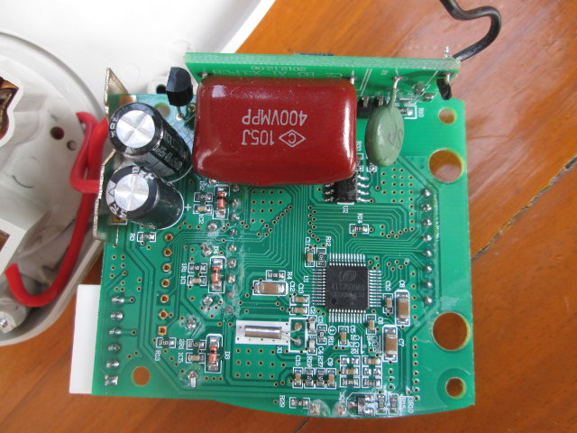
The PCB is called CZ-7039-B2, and the top includes the display, 4 user buttons, as well as JTAG through holes (P2) and 2.54mm header (P1) with TDO, TMS, GND and 3.3V signals, as well as a pin called P1600, but I still haven’t found out what it might be for.

I’ve also taken the board out completely, to find out everything is basically handled by a single 48-pin chip called ATT7039AU.
After a Google search, I quickly found out the chip is made by Shanghai based HiTrend Technology that specializes in Energy Monitoring chips based on ARM Cortex M0 or 8051 cores, and ATT7039AU datasheet is there for anybody to download, but unfortunately it’s mostly in Chinese, except diagrams.

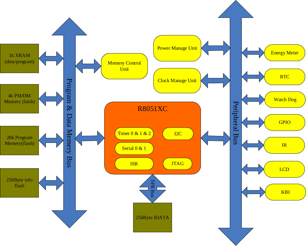
The chip uses a 8051 MCU core, with I2C, serial, timers, JTAF, and interrupt services runtime, and integrates 32KB flash, and 1KB XRAM. Peripheral support include an LCD interface with 8com x 12seg or 4com x 16seg, GPIOs, IR, RTC, and of course the energy meter unit.

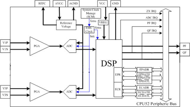
A more detailed block diagram about the energy meter unit shows 4 inputs with V1P & V1N current signal inputs, V3P & V3N voltage signal inputs, and two outputs: PF anf QF, which are apparently used for calibration, as explained in paragraphs 4.3 of the datasheet.
You’ll also find a reference schematic, a FAQ, and SDKs using ARM Keil on the product page. So there’s probably all you need to know to design your own power meter, and ATT7039A can also be easily purchased on Aliexpress for less than $5 shipped, obviously much less in larger quantities.
One potential interesting application would be a WiFi power monitor for example combining ESP8266 with ATT7039U. Although products such as Broadlink SP2 can already monitor energy usage, and send data to the cloud, which can then be accessed from a mobile app, they are not as flexible as they could be, and mine only worked a few months.

Jean-Luc started CNX Software in 2010 as a part-time endeavor, before quitting his job as a software engineering manager, and starting to write daily news, and reviews full time later in 2011.
Support CNX Software! Donate via cryptocurrencies, become a Patron on Patreon, or purchase goods on Amazon or Aliexpress


