Yesterday, one person asked me to make a video showing GPIO control on Orange Pi 2 mini on YouTube, and since I have just completed a post about Orange Pi camera, I thought it might be fun to check GPIO support too. This post focuses on Allwinner H3 boards, but the instructions and status should be very similar for Allwinner A20 and A31s versions.
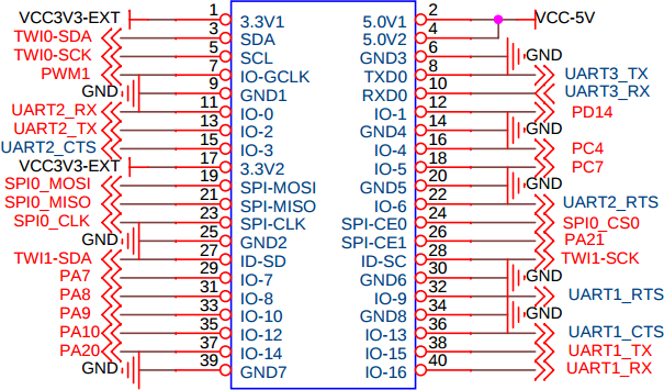
One of the first things you want before starting playing with GPIOs is the expansion header’s pinout chart, and I could not find any until I had the idea to check for schematics, which are available on Orange Pi resources page. I downloaded the schematics for Orange Pi 2, which should be the same as for Orange Pi 2 mini as the only difference is the lack of WiFi module. Orange Pi PC is a little different, and the schematics are nowhere to be found, but it would be surprising if the 40-pin connector had a different layout.
Some documentation would be nice too, and there’s a WiringPi for Orange Pi page in the wiki, which points to WiringOP on github, but unfortunately it does not exist [Update Nov 3, 2015: WiringOP is up on Github with the last changes 4 days ago]. A more generic GPIO page refers to RPi.GPIO, BCM2835 and WebioPi libraries, but again those sections are empty. After cheking in the forums, it seems there’s no GPIO library for Orange Pi boards. If somebody is interested in working on a GPIO library for Orange Pi, starting with LeMaker’s WiringBP for Banana Pro might be a good idea, as GPIO, SPI and I2C support is implemented. Banana Pro is based on Allwinner A20, so some registers and addresses might be different, but required technical information should be available in Allwinner H3 datasheet.
So instead I used sysfs to control the board’s I/Os. GPIO (gpio-sunxi), SPI (spi-sunxi), and I2C (i2c-sunxi) drivers are pre-installed in the Debian Jessie image I installed in Orange Pi 2 mini board, but today, I only played with GPIO on my board.
Using sysfs is pretty easy:
|
1 2 3 4 5 6 7 8 |
su modprobe gpio-sunxi ls /sys/class/gpio_sw/ normal_led PA10 PA13 PA18 PA20 PA6 PA9 PC2 PC7 PG7 PL10 PA0 PA11 PA14 PA19 PA21 PA7 PC0 PC3 PD14 PG8 standby_led PA1 PA12 PA15 PA2 PA3 PA8 PC1 PC4 PG6 PG9 echo 1 > /sys/class/gpio_sw/standby_led/data echo 0 > /sys/class/gpio_sw/standby_led/data |
The few commands above load the GPIO driver, list the GPIOs, and turn on and off a green LED (D7) on the board.
To film a more entertaining video, I used the LED board from my Raspberry Pi perfboard enclosure which I connected to 9 GPIOs on the board, as well as 5V and GND. You can ignore IO-0, IO-2 on the schematics at the top, as only the pin numbers (1 – 40) are used to wire the boards, and PA7, PA8, etc… are used to control the GPIOs from Linux.
I’ve written a shell script that turn on each LED, or group of LEDs, one by one every second, before turning them off every second in an infinite loop. That’s the result.

Jean-Luc started CNX Software in 2010 as a part-time endeavor, before quitting his job as a software engineering manager, and starting to write daily news, and reviews full time later in 2011.
Support CNX Software! Donate via cryptocurrencies, become a Patron on Patreon, or purchase goods on Amazon or Aliexpress