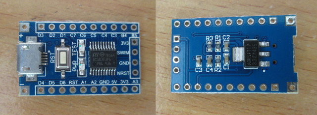
In January, I discovered there was such thing as a one dollar development board based on STMicro STM8S103F3P6 8-bit MCU with 1KB SRAM, 8KB flash, and 640 bytes EEPROM, some GPIOs as well as I2C, UART, SPI, ADC, and PWM signals. Links to documentation and source code were provided, but development tools were only Windows based. However, one of my reader informed me SDCC (Small Devices C Compiler) supported STM8, and development in Linux should be feasible. So I decided to buy the board on eBay for $1.62, as well as an ST_link V2 programmer for STM8 / STM32 for $4.52 in order to flash the firmware.
The board came pretty quickly, i.e. within 2 to 3 weeks.
 But due to a lost package, the programmer took nearly 3 months to reach me, as the seller had to re-send after I failed to receive it within 2 months.
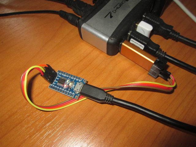
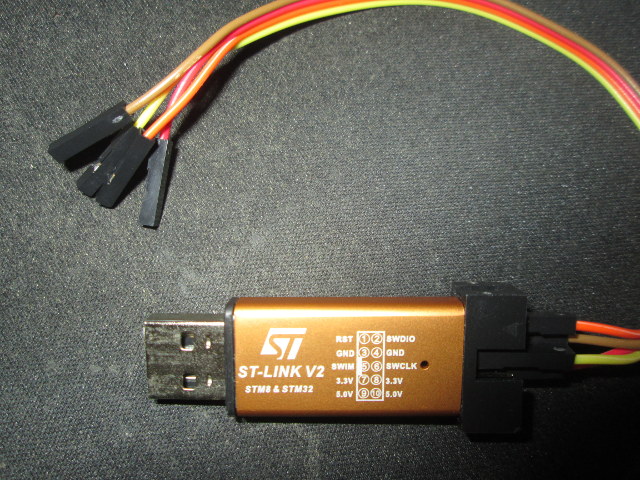 It comes with 4 wires that need to be connected to RST/NRST, 3.3V, SWIM, and GND. To do so, I had to solder a 4-pin header on the side of the board.
To get started with STM8 on Linux, I found some information on ColeVision website where they explained how to run Drystone on STM8/128-EVAL board using SDCC as the compiler, and stm8flash to program the board.
So I’ve given it a try on Ubuntu 14.04 with the simple goal of blinking the TEST LED on the board. sdcc is an Ubuntu package, so it’s pretty easy to install:
|
1 |
sudo apt-get install sdcc |
Let’s check the version and some more information:
sdcc --version

SDCC : mcs51/gbz80/z80/z180/r2k/r3ka/ds390/pic16/pic14/TININative/ds400/hc08/s08 3.3.0 #8604 (Dec 30 2013) (Linux)
That’s version 3.3.0 released in December 2013 and it lacks STM8 supports, but the latest version (sdcc v3.4.0) has been released in April 2014, and we can get it with a PPA, so let’s use that one instead:
|
1 2 3 4 |
sudo add-apt-repository ppa:laczik/ppa sudo apt-get update sudo apt-get remove sdcc sdcc-libraries sudo apt-get install sdcc |
If you are using Ubuntu 14.10 or greater, you’ll already get the latest version.
Let’s double check stm8 is indeed supported:
sdcc --version

SDCC : mcs51/z80/z180/r2k/r3ka/gbz80/tlcs90/ds390/pic16/pic14/TININative/ds400/hc08/s08/stm8 3.4.0 #8981 (Jan 10 2015) (Linux)

published under GNU General Public License (GPL)
Great! stm8 is now present in the list of supported MCUs.
For the next step was to install stm8flash tool to program the device:
|
1 2 3 4 |
git clone https://github.com/vdudouyt/stm8flash.git cd stm8flash make sudo make install |
Now I had to find some code samples to blink the LED. I started but checking the samples for ST Visual Programmer and IAR tools, combine with a modified version of Drystone source code, but I always had some issues with the header files, and it seems a bit more work than expected. But then I discovered that Valentin Dudouyt, stm8flash developer, also provided code samples in his github account, including a blinky sample:
|
1 2 |
git clone https://github.com/vdudouyt/sdcc-examples-stm8.git cd sdcc-examples-stm8 |
First, I tried to compile the samples, and they failed because sp_test.c was missing, so I edited the Makefile to remove sp_test.ihx, and build was successful. The LED on the board is connected to B5 GPIO, so at that point I had to check out STM8S103F3 datasheet to find out more about the registers used in the sample. The register map is in section 6.2 of the document, and I need to use three registers:
- PB_ODR – Port B data output latch register (Sets pin HIGH or LOW)
- PB_DDR – Port B data direction register (Sets direction to INPUT or OUTPUT)
- PB_CR1 – Port B control register 1
Since pin 5 correspond to 00100000 (0x20) I updated blinky.c sample as follows:
|
1 2 3 4 5 6 7 8 9 10 11 12 13 |
#include "stm8l.h" int main() { int d; // Configure pins PB_DDR = 0x20; PB_CR1 = 0x20; // Loop do { PB_ODR ^= 0x20; for(d = 0; d < 29000; d++) { } } while(1); } |
I typed make again to generate an updated firmware (blinky.ihx), and flash it as follows:
|
1 2 3 4 |
stm8flash -c stlinkv2 -p stm8s103 -w blinky.ihx Determine FLASH area Writing Intel hex file 189 bytes at 0x8000... OK Bytes written: 189 |
All good and the LED started blinking…
So now you should be able to write simple program to control other GPIOs, I2C, SPI, UART with the board. But if your program is a little more complex a debugger could be useful, and there’s Texane STLink working on Windows, Mac, and Linux, that can run gdbserver for STM32… But I tried it for STM8.
|
1 2 3 4 |
git clone https://github.com/texane/stlink cd stlink ./autogen.sh make -j8 |
Then I ran st-link:
|
1 2 3 4 |
./st-util 2015-04-13T16:44:34 INFO src/stlink-usb.c: -- exit_dfu_mode 2015-04-13T16:44:34 INFO src/stlink-common.c: Loading device parameters.... 2015-04-13T16:44:34 WARN src/stlink-common.c: unknown chip id! 0xe0042000 |
Hmmm, it does not look good, and sadly there’s no support for STM8 yet, as STM32 and STM8 use different interfaces (SWD vs SWIM).
So if you have troubles debugging your program, you may have to revert to Windows based tools, at least for now, unless you’re up for the task and want to add STM8 support to Texane.

Jean-Luc started CNX Software in 2010 as a part-time endeavor, before quitting his job as a software engineering manager, and starting to write daily news, and reviews full time later in 2011.
Support CNX Software! Donate via cryptocurrencies, become a Patron on Patreon, or purchase goods on Amazon or Aliexpress