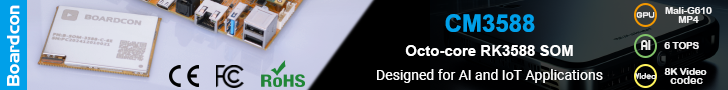
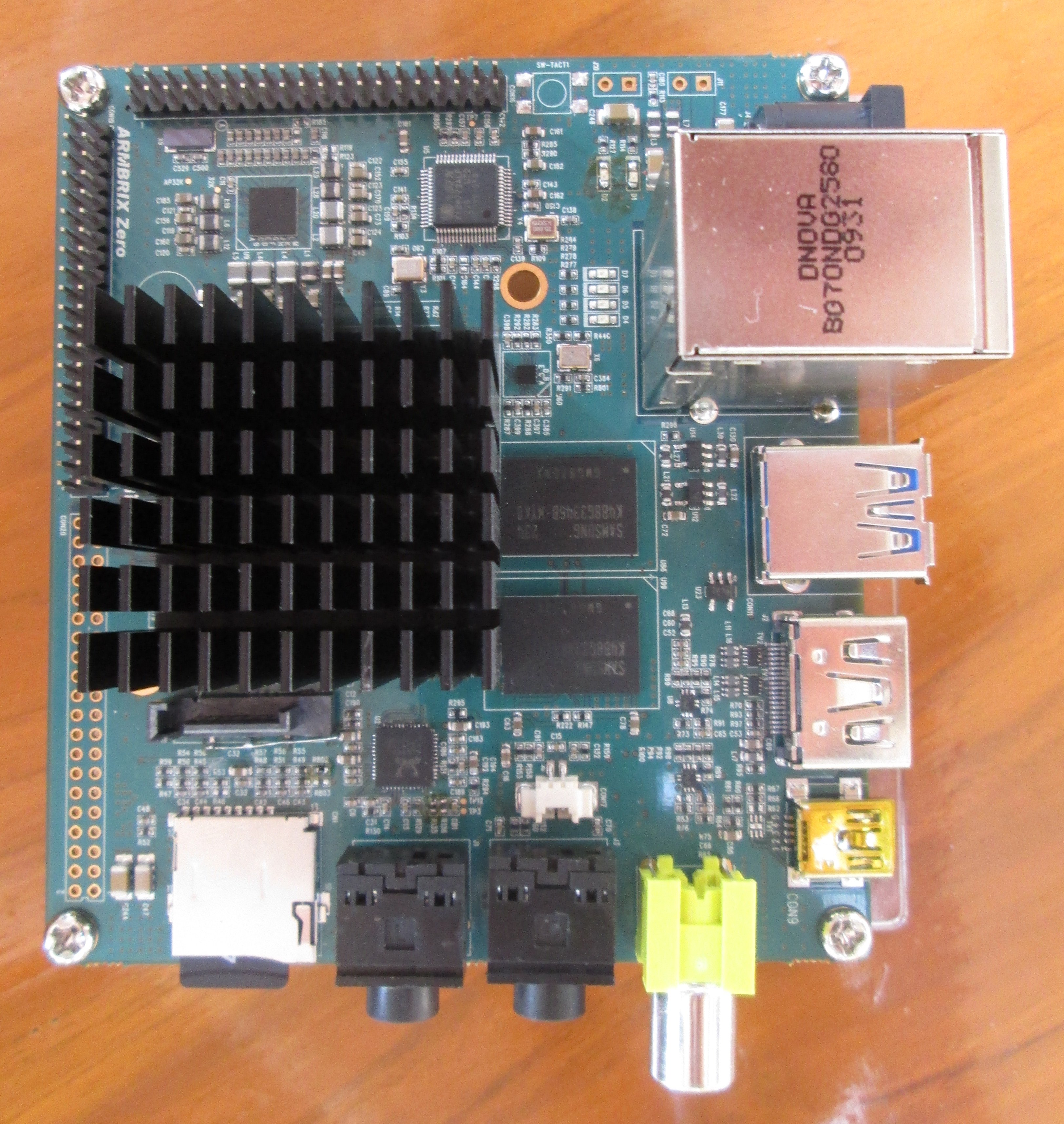
I’ve just received an early sample of ARMBRIX Zero (aka ARMBRIX-5250-A), a development board based on Samsung Exynos 5250 dual cortex A15 processor with 2GB RAM, a microSD slot, 1x USB 3.0, 2x USB 2.0 Host, 1x USB Device, 10/100 Ethernet, HDMI output, SATA 3.0, some Audio I/O ports, and 3 expansions headers. This is basically a low cost version of the Arndale board, with things such as eMMC 4.5 (Sorry I’ve missed the eMMC socket at the back of the board) sensors missing.
Today, I won’t turn the board on (I’ll explain why at the end of the post), but instead show some pictures of the development and debug boards.
If you had previously seen the board picture before, you’ll noticed it has a grown a heatsink. The heatsink is probably here to stay, but may be slightly different (e.g. lower) when you receive your board. The bottom acrylic plate won’t be part of the board you’ll receive in case you wonder. The board came with a microSD card loaded with Android Jelly Bean (4.1).
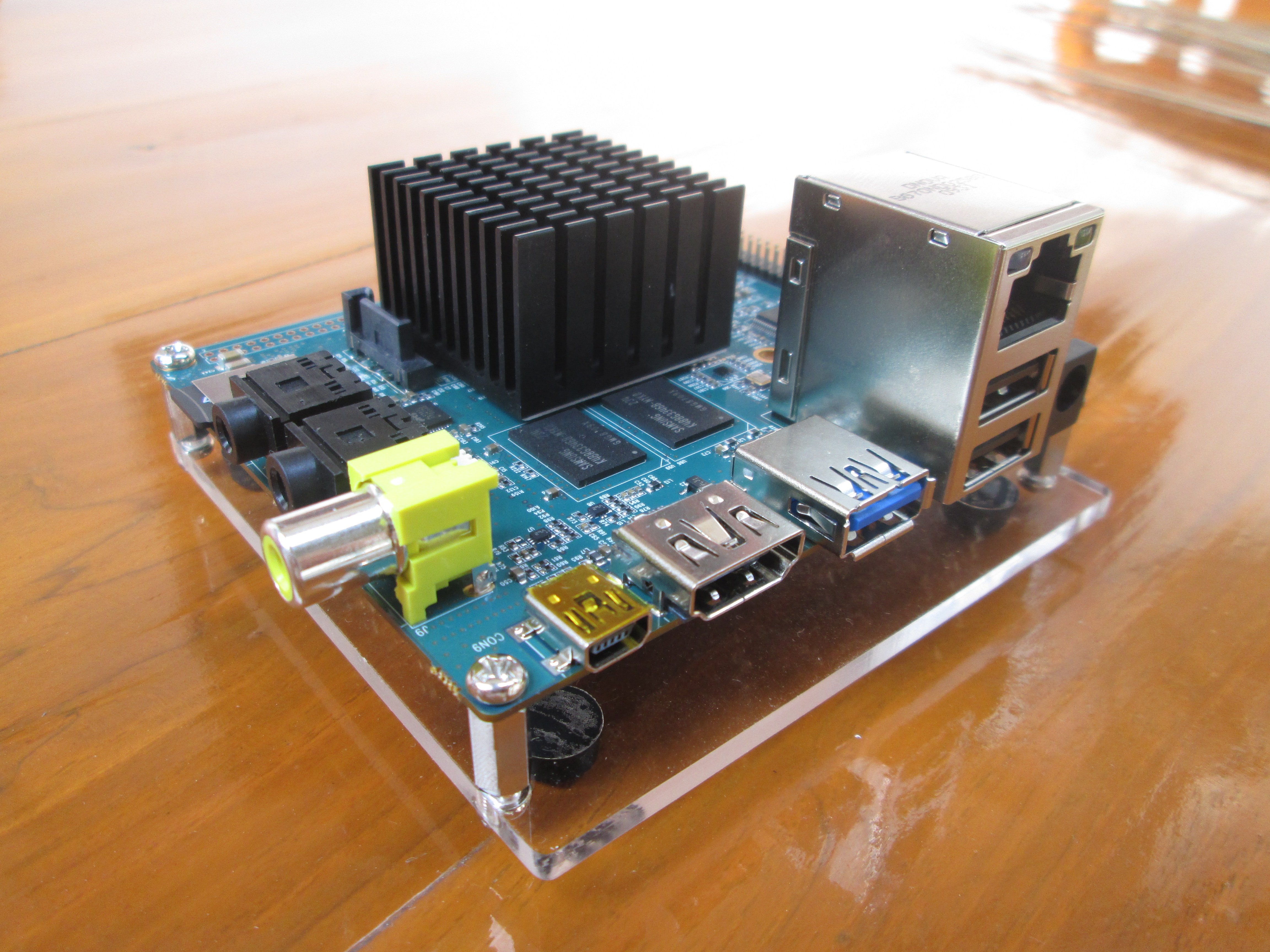
The board has three expansion headers, but only CON16 (MIPI Master/Slave, 1x I2C, GPIO) and CON19 (3x serial interfaces, 2x I2C, 2x ADC, JTAG, USB, MMC, and reset) are soldered. CON20 provides access to I2S, Interrupt and GPIO pins, and the System bus (EBI). Pin descriptions for all 3 headers are available in this PDF. (This is an early version, and there may be changes before final release, but this should give you an idea). this PDF

The package included a debug board with 2 DB9 connectors that gives access to UART2 (CON2) for serial console, UART3 (CON3), and a JTAG connector. Currently, ARMBRIX does not plan to sell this board, but if there is enough demand, they may change their mind. You just need to connect it to CON16 on the development board, and connect CON2 to your computer serial port via a null modem cable to access the serial console.

But since I don’t have a null modem cable at home, and my PC does not come with a serial port. I’ll just use the TTL to USB debug board I’m using with other boards and devices.
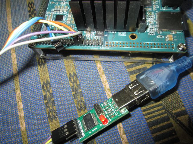
You just need to connect 3 pins from CON19 to your debug board. Pin 13 to GND, Pin 14 (Rx) to Tx, and Pin 16 (Tx) to Rx. That means ARMBRIX debug board may not be needed for most people.
I would have liked to show the board boot, run some benchmark, and talk about its performance, but it won’t boot because I only have a 5V/2A power supply, and as mentioned in the board description, a 5V/3A power supply is recommend. If you plan to connect a SATA hard drive, and/or an external LCD you’d probably need even more power. ARMBRIX told me they use a 5V/5A for testing.
The next step is to go shopping, and hopefully I’ll be able to show you much more.

Jean-Luc started CNX Software in 2010 as a part-time endeavor, before quitting his job as a software engineering manager, and starting to write daily news, and reviews full time later in 2011.
Support CNX Software! Donate via cryptocurrencies, become a Patron on Patreon, or purchase goods on Amazon or Aliexpress